Optimization Problems
This section describes our proposed benchmark optimization problems to be applied to the STW. The problems build on one another with the intention of allowing researchers to test their tools on increasingly complex problems:
Case 1: Structural mass minimization with a fixed geometry.
Case 2: Fuel burn minimization with a fixed wing planform.
Case 3: Fuel burn minimization with a variable wing planform.
Case 4: Fuel burn minimization with a variable wing planform and additional performance constraints.
Table 4 and Table 5 list information about the aircraft and the flight conditions used in the optimization problems, which are all based on publicly available data on the high gross-weight variant of the Boeing 717.
Quantity |
Description |
Value |
|
|---|---|---|---|
Baseline wing geometry |
|||
\(b\) |
Semispan |
\(14\,\text{m}\) |
|
\(C_\text{root}\) |
Root chord |
\(5\,\text{m}\) |
|
\(C_\text{tip}\) |
Tip chord |
\(1.5\,\text{m}\) |
|
\(S\) |
Planform area (single wing) |
\(45.5\,\text{m}^2\) |
|
\(\text{MAC}\) |
Mean aerodynamic chord |
\(3.56\,\text{m}\) |
|
Masses |
|||
\(M_\text{payload}\) |
Payload mass |
\(14.5e3\,\text{kg}\) |
|
\(M_\text{frame}\) |
Operating empty mass (minus wing) |
\(25e3\,\text{kg}\) |
|
\(M_\text{fuel, res}\) |
Reserve fuel mass |
\(2e3\,\text{kg}\) |
|
Fuelburn calculation parameters |
|||
\(R\) |
Nominal range |
\(3815\,\text{km}\) |
|
\(R_\text{climb}\) |
Climb segment range |
\(290\,\text{km}\) |
|
\(V_\text{climb}\) |
Average climb speed |
\(350\,\text{mph}\) |
|
\(C_{D,\text{frame}}\) |
Airframe drag coefficient (fuselage + tail + nacelle) |
\(0.01508\) |
|
\(k_\text{tank}\) |
Assumed fraction of wingbox that can store fuel |
\(0.85\) |
|
\(V_\text{aux}\) |
Auxilliary fuel tank volume |
\(2.763\,\text{m}^{3}\) |
|
\(\text{TSFC}\) |
Thrust specific fuel consumption |
\(18e-6\,\text{kg}/\text{N\,s}\) |
|
\(\rho_\text{fuel}\) |
Fuel density |
\(804\,\text{kg}/\text{m}^3\) |
Flight point |
Altitude |
Mach number |
Load factor |
Aircraft mass |
|---|---|---|---|---|
Cruise |
\(10400\,\text{m}\) |
0.77 |
1 |
\(\sqrt{M_\text{cruise, start}\times LGM}\) |
Pull-up Maneuver |
\(0\,\text{m}\) |
0.458 |
2.5 |
\(LGM\) |
Push-down Maneuver |
\(0\,\text{m}\) |
0.458 |
-1 |
\(LGM\) |
High Lift Buffet |
\(37000\,\text{ft}\) |
0.82 |
1.3 |
\(M_\text{cruise, start}\) |
High Speed Buffet |
\(37000\,\text{ft}\) |
0.89 |
1 |
\(M_\text{cruise, start}\) |
Objectives
The objective function to be minimized in Case 1 is the wingbox mass, computed from the FE model. The objective function for cases 2 and 3 is the fuel burn over a given mission. The fuel burn is computed using a two-stage process that accounts for the fuel burn in both cruise and climb. This process starts by computing the landing gross mass (\(\text{LGM}\)):
The total mass of a single wing is computed using the regression model created by Mariens et al. [MEVanTooren13]:
Where \(M_\text{wingbox}\) is the wingbox mass.
Assuming the fuel burn during descent and landing is negligible, the mass at the start of the cruise phase, and then the takeoff gross mass (\(\text{TOGM}\)) are computed by rearranging the Breguet range equation:
Where \(\gamma\) is the climb angle (SI{2.054}{degree}), computed based on the assumed climb range and cruise altitude given in Table 4 and Table 5.
The lift and drag in the cruise condition are computed using an aeroelastic analysis, the values are doubled to get the full aircraft values, and the drag of un-modeled components (fuselage, tail, and nacelles) is added:
Where \(C_{D,\text{frame}}\) is estimated using a conceptual drag build-up implemented by Adler and Martins [AM23] based on the methods of Torenbeek [Tor90] and Raymer [Ray92]. \(S\) is the baseline single wing planform area from Table 4 and does not vary during optimization since we assume that the remainder of the aircraft remains identical.
Design Variables
The primary differences between the three benchmark problems are the amount of design freedom given to the optimizer through the design variables. Table 6 summarizes these design variables. Note that, the exact number and form of some design variables will depend on the structural modeling and geometric parameterization approaches used, as is explained in the following sections.
Variable |
Case 1 |
Case 2 |
Cases 3 & 4 |
|---|---|---|---|
Structural sizing |
\(\checkmark\) |
\(\checkmark\) |
\(\checkmark\) |
Pull-up maneuver angle of attack |
\(\checkmark\) |
\(\checkmark\) |
\(\checkmark\) |
Push-down maneuver angle of attack |
\(\checkmark\) |
\(\checkmark\) |
\(\checkmark\) |
Cruise angle of attack |
\(\checkmark\) |
\(\checkmark\) |
|
Twist distribution |
\(\checkmark\) |
\(\checkmark\) |
|
Section shapes |
\(\checkmark\) |
\(\checkmark\) |
|
Chord distribution |
\(\checkmark\) |
||
Span |
\(\checkmark\) |
||
Sweep |
\(\checkmark\) |
Structural Variables
Due to the variety of structural modeling approaches we want to support in these benchmark problems, we do not prescribe a specific set of structural sizing variables. Instead we specify the following requirements for the parameterization of the wingbox:
A stiffener pitch of \(150\,\text{mm}\) should be used on all panels.
Each rib, and each skin and spar segment between a pair of ribs, should be treated as a separate panel with its own structural sizing variables, as shown in Fig. 6.
The parameterization should allow the optimizer to vary the thickness of the panels.
The parameterization should allow the optimizer to vary the thickness of stiffeners, and ideally their cross-section dimensionsfootnote{If parameterizing the stiffener cross-section, we recommend participants link the flange width, \(W_\text{stiff}\), to the web height, \(h_\text{stiff}\) (e.g keeping \(w_\text{stiff} = h_\text{stiff}\)) rather than treating it as a separate variable.
This structural parameterization should remain the same for all three optimization problems.
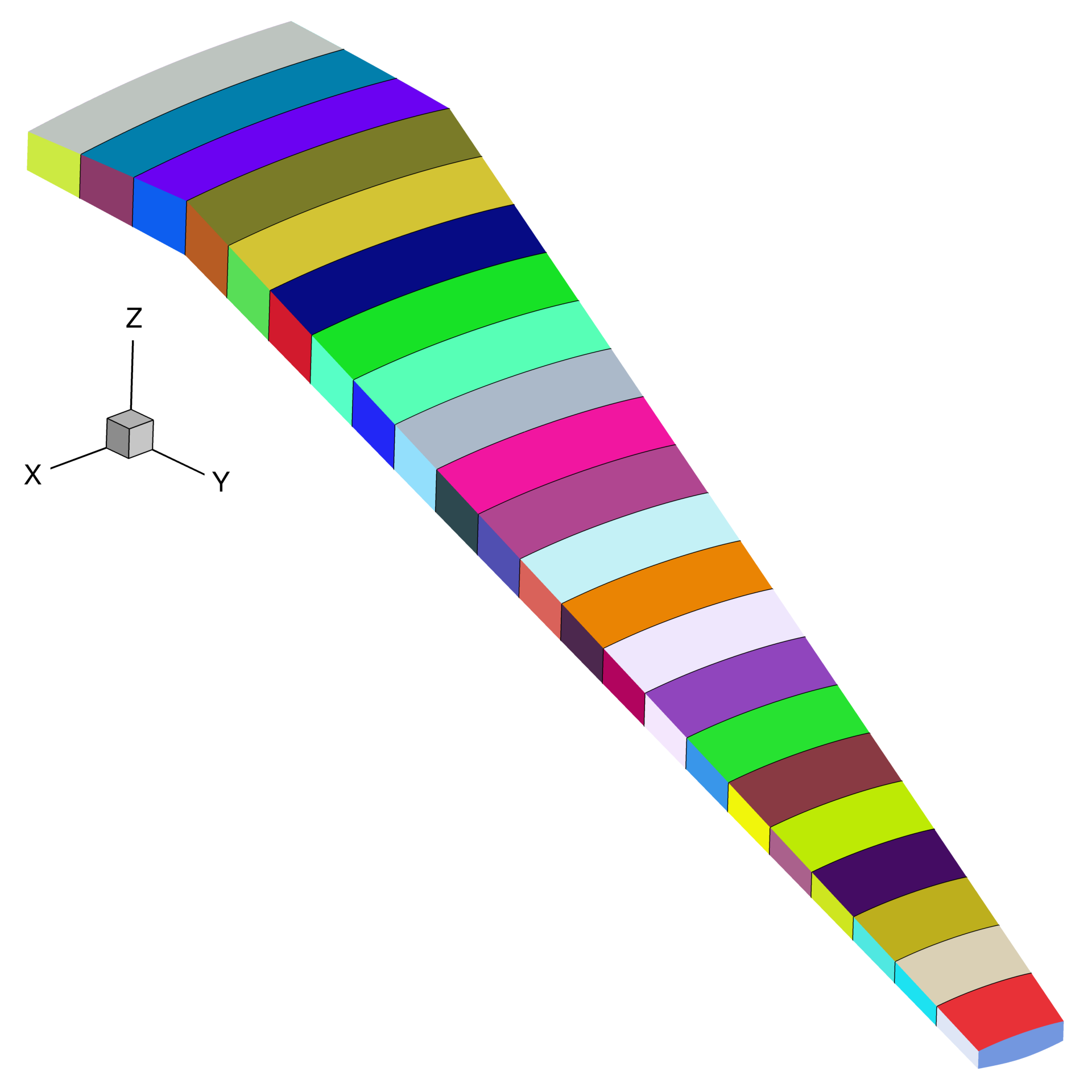
Fig. 6 Each separately colored wingbox panel should be given it’s own structural sizing variables.
Geometric Variables
In Case 1, the wing geometry is fixed and thus there are no geometric design variables. In Case 2, the section shapes of the wing may be changed in the z direction, and the twist distribution may be varied. In Case 3, the optimizer may also vary the span, sweep, and chord distribution. The parameterization method used to achieve these changes (e.g FFD, CAD etc) and the level of detail (e.g number of values used to define the twist distribution) are left free. However, the following requirements must be satisfied:
The twisting must occur about the leading edge of the wing.
The root of the wing (at the symmetry plane) must not be twisted.
The shape changes must be parameterized in a manner that does not allow the optimizer to achieve twisting of the section shapes.
The SOB junction of the wingbox should not move in the y direction.
The leading edge of the wing must remain straight, save for a potential break at the SOB junction.
Aerodynamic Variables
Finally, the optimizer can control the angles of attack at each flight point to meet the lift constraints described in the Constraints section.
Constraints
Table 7 provides a high-level summary the constraints applied in the 3 benchmark problems. As with the design variables, the exact formulation of the constraints in each benchmark problem will depend to some extent on the structural modeling and geometric parameterization approaches used by participants.
Structural Constraints
The primary structural constraints enforce that the wingbox has a safety factor of 1.5 to both material and buckling failure in both maneuver flight conditions. How this is achieved is left free.
Adjacency constraints are enforced to avoid abrupt changes in panel sizing. The change in panel and stiffener thicknesses between adjacent skin and spar panels is limited to \(2.5\,\text{mm}\) and the change in stiffener height to \(10\,\text{mm}\). (By this we mean that the difference between variables on two adjacent skin panels, or two adjacent spar panels, are constrained, but not the difference between a spar panel and an adjacent skin panel.) Some basic structural sizing rules suggested by Kassapoglou [Kas13] should be used on all panels:
The skin and stiffener thicknesses should be at least \(0.6\,\text{mm}\)
The stiffener heights should be at least \(18\,\text{mm}\)
The stiffener flange widths should be at least \(25.4\,\text{mm}\)
The aspect-ratio of the stiffener web (\(h_\text{stiff}/t_\text{stiff}\)) should be between 5 and 30.
The thickness of the stiffener flanges on a panel should be no more than 15 times the panel thickness.
The stiffener flange width should be less than the stiffener pitch to avoid overlapping flanges.
Participants should enforce as many of these constraints as are applicable to their structural sizing parameterization in all three benchmark problems.
Taxi Bump Constraints
For case 4, a taxi bump load case simulates the effect of a rough runway, and can be applied as pure inertial loads to the wingbox, at load factors of plus and minus 2g, as suggested by Niu [Niu88]. These load cases should be applied for a wing with full fuel. As with the maneuver flight conditions, structural constraints should be attached to each taxi bump load case, for a safety factor of 1.5 to both material and buckling failure.
Geometric Constraints
Since the benchmark problems consider a limited selection of flight points, additional geometric constraints are required to ensure the optimizer produces a realistic wing geometry:
The wing’s leading edge radius must be at least 90% of its baseline value throughout the span to maintain reasonable low-speed performance.
The front and rear spars must be at least 75% of their baseline height throughout the span to maintain the space required to mount components such as control surface actuators [LKM15].
The region between the rear spar and the trailing edge must be at least 50% of its baseline thickness to prevent the optimizer creating an unrealistically thin trailing edge.
The wingbox volume must be large enough to store the amount of fuel required for the mission, as computed in the objective function.
When the planform is varied, the wing loading \(\left(\text{TOGM}/2S\right)\) must be no greater than \(600\,\text{kg} / \text{m}^2\).
When computing the fuel volume constraint, the total available fuel tank volume is the auxiliary tank volume plus the fraction of both wingboxes that is assumed to be available for fuel storage, the constraint can therefore be written as:
or:
which is better scaled. Note that the total fuel mass, \(M_\text{fuel}\), is the sum of the fuel burn computed using (1) and the reserve fuel mass given in Table 4.
Lift Constraints
The lift produced by the wing at each flight point must be equal to the aircraft weight multiplied by the relevant load factor. The maneuvers are assumed to be performed at the LGM since the inertial relief of the fuel is not included in the structural model. The aircraft mass for the cruise condition is taken to be the mid-cruise mass, which is the geometric average of the cruise start and end masses. This accounts for the non-uniform rate of fuel burn over the segment.
Buffet Onset Constraints
For case 4, a buffet constraints are added. These constraints enforce that the wing must be free from buffet at a load factor of 1.3 up to its maximum operating Mach number, \(M_\text{MO}=0.82\), and up to the dive Mach number, \(M_D=0.89\), at a load factor of 1. As shown in Table 5, both these constraints are applied at the aircraft’s service ceiling of \(37000\,\text{ft}\) and at the starting cruise mass, \(M_\text{cruise, start}\) (see the fuel burn objective computation).
Participants are free to implement these buffet constraints as they wish, we provide a semi-empirical model here based on the method of Berard and Isikveren [BI09]. This model computes the buffet onset lift coefficient (\(C_{L_\text{buffet}}\)) for a range of Mach numbers based on some basic geometric parameters of the wing. The constraint for both buffet conditions can then be written as:
Where \(C_{L,n}\) is the lift coefficient required to produce the necessary load factor at each buffet flight point and \(C{L_\text{buffet}}\) is the buffet onset lift coefficient at the relevant Mach number for each flight point.
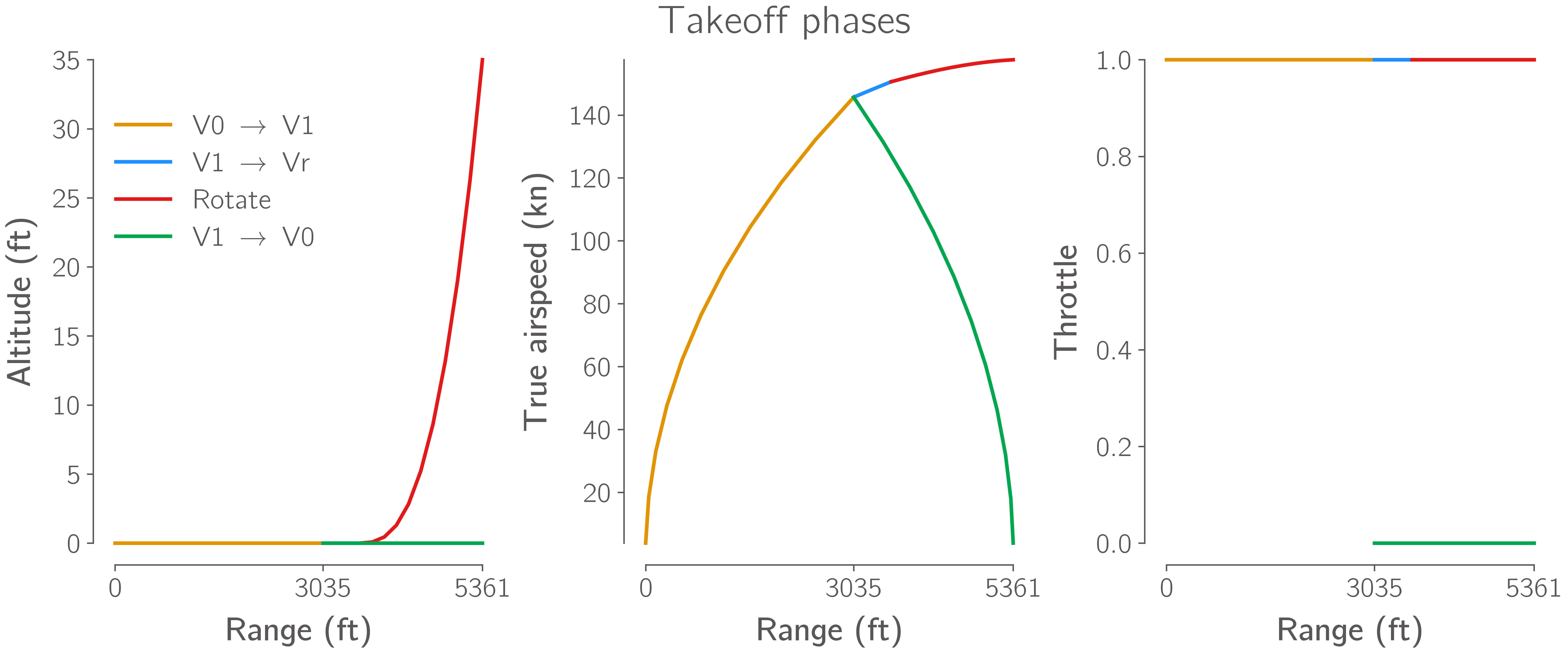
Takeoff Constraint
The balanced field length of the aircraft at its TOGM, on a dry runway, at sea-level standard temperature conditions must be less than 5500 ft. The balanced field length is the distance required for the aircraft to accelerate, takeoff, and climb to 35 ft above the runway. An engine failure is assumed to occur at the “decision speed”, v1, this decision speed must be solved for such that the distance required to continue the takeoff and climb to 35 ft is equal to the distance required to stop the aircraft.
The figure below shows an example of the phases of such a balanced field length calculation:
Participants are free to compute this balanced field length constraint using any method they choose, we provide a simple model with analytic gradients that participants may use here.
The rotation speed of the aircraft should be 110% of its stall speed.
Computing this stall speed requires participants to compute the maximum lift coefficient of the wing in it’s takeoff configuration.
To do this, participants can find assumed details of the size and location of slats and flaps on the STW in wingGeometry.py, provided in our Simple Transonic Wing Files.
A 20 degree flap setting should be assumed for the entire calculation.
The provided model mentioned above includes a simple estimation of the maximum lift coefficient based on high level wing geometry parameters and an assumed sectional maximum lift coefficient.
Constraints Summary
Constraint | Description |
Case 1 |
Case 2 |
Case 3 |
Case 4 |
||
|---|---|---|---|---|---|---|
\(SR_\text{2.5g} \leq 1 / 1.5\) |
Pull-up maneuver strength ratio |
\(\checkmark\) |
\(\checkmark\) |
\(\checkmark\) |
\(\checkmark\) |
|
\(SR_\text{-1g} \leq 1 / 1.5\) |
Push-down maneuver strength ratio |
\(\checkmark\) |
\(\checkmark\) |
\(\checkmark\) |
\(\checkmark\) |
|
\(\left|t_{\text{panel},i} - t_{\text{panel},j}\right| \leq 2.5 \text{mm}\) |
Skin/spar panel thickness adjacency |
\(\checkmark\) |
\(\checkmark\) |
\(\checkmark\) |
\(\checkmark\) |
|
\(\left|t_{\text{stiff},i} - t_{\text{stiff},j}\right| \leq 2.5 \text{mm}\) |
Skin/spar stiffener thickness adjacency |
\(\checkmark\) |
\(\checkmark\) |
\(\checkmark\) |
\(\checkmark\) |
|
\(\left|h_{\text{stiff},i} - h_{\text{stiff},j}\right| \leq 10 \text{mm}\) |
Skin/spar stiffener height adjacency [a] |
\(\checkmark\) |
\(\checkmark\) |
\(\checkmark\) |
\(\checkmark\) |
|
\(t_{\text{stiff},i} \leq 15 t_{\text{panel},i}\) |
Maximum stiffener thickness [a] |
\(\checkmark\) |
\(\checkmark\) |
\(\checkmark\) |
\(\checkmark\) |
|
\(h_{\text{stiff},i} \leq 30 t_{\text{stiff},i}\) |
Maximum stiffener aspect-ratio [a] |
\(\checkmark\) |
\(\checkmark\) |
\(\checkmark\) |
\(\checkmark\) |
|
\(h_{\text{stiff},i} \geq 5 t_{\text{stiff},i}\) |
Minimum stiffener aspect-ratio [a] |
\(\checkmark\) |
\(\checkmark\) |
\(\checkmark\) |
\(\checkmark\) |
|
\(w_{\text{stiff},i} \leq p_{\text{stiff},i}\) |
Minimum stiffener spacing [a] |
\(\checkmark\) |
\(\checkmark\) |
\(\checkmark\) |
\(\checkmark\) |
|
\(L_\text{2.5g} = 2.5 LGM g\) |
Pull-up maneuver lift level |
\(\checkmark\) |
\(\checkmark\) |
\(\checkmark\) |
\(\checkmark\) |
|
\(L_\text{-1g} = -LGM g\) |
Push-down maneuver lift level |
\(\checkmark\) |
\(\checkmark\) |
\(\checkmark\) |
\(\checkmark\) |
|
\(L_\text{cruise} = M_\text{mid-cruise} g\) |
Cruise lift level |
\(\checkmark\) |
\(\checkmark\) |
\(\checkmark\) |
||
\(t_\text{spar} \geq 0.75 t_{\text{spar},0}\) |
Minimum Spar height |
\(\checkmark\) |
\(\checkmark\) |
\(\checkmark\) |
||
\(t \geq 0.5 t_{0}\) |
Minimum TE thickness |
\(\checkmark\) |
\(\checkmark\) |
\(\checkmark\) |
||
\(R_\text{LE} \geq 0.9 R_{\text{LE},0}\) |
Minimum Leading edge radius |
\(\checkmark\) |
\(\checkmark\) |
\(\checkmark\) |
||
\(M_\text{fuel}/\rho_\text{fuel} \leq V_\text{aux} + 2k_\text{tank} V_\text{wingbox}\) |
Fuel volume |
\(\checkmark\) |
\(\checkmark\) |
\(\checkmark\) |
||
\(TOGM / 2S \leq 600 \text{kg}/\text{m}^{2}\) |
Maximum wing loading |
\(\checkmark\) |
\(\checkmark\) |
|||
\(BFL \leq 5500 \text{ft}\) |
Maximum balanced field length |
\(\checkmark\) |
||||
\(C_{L,1.3g} \leq C_{L_\text{buffet},M=0.82}\) |
Buffet onset margin - High lift condition |
\(\checkmark\) |
||||
\(C_{L,1g} \leq C_{L_\text{buffet},M=0.89}\) |
Buffet onset margin - High speed condition |
\(\checkmark\) |
||||
\(SR_\text{2.0g} \leq 1 / 1.5\) |
Taxi bump strength ratio (full fuel, no aerodynamics) |
\(\checkmark\) |
||||
\(SR_\text{-2.0g} \leq 1 / 1.5\) |
Taxi bump strength ratio (full fuel, no aerodynamics) |
\(\checkmark\) |
||||